Home
Jeremy Fleischman
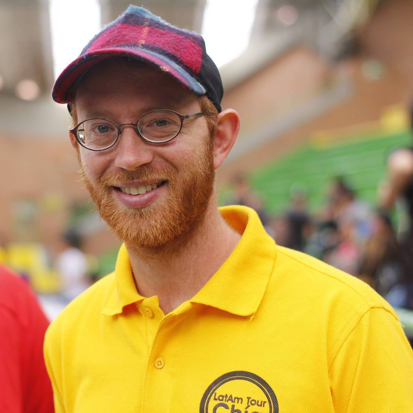
I’m a programmer based in the San Francisco Bay Area.
I like making computers do things. I believe Nix is the one of the best tools to make computers do things. As a result, I spend a lot of my time contributing to the Nix ecosystem.
I’m open to freelance work. Feel free to contact me if you have a project you would like help with.
I also have other hobbies, but programming is the one that pays the bills. I occasionally blog about my projects.
Nix community projects
In no particular order:
- Leader of the Nix Formatting Team
- Member of the NixOS Infrastructure Team
- Co-organizer the Bay Area Nix User Group
- treefmt maintainer
- nixpkgs maintainer
- flake-input-patcher author
- none-ls nix_flake_fmt builtin author (Neovim
nix fmtautoformatting plugin)