Dialup Stackmat
August 21, 2014For those of you who have never been to a Rubik’s Cube competition, they are controlled chaos. It goes something like this:
- A competitor is called to bring up his solved cube and place it on a blank scorecard.
- A scrambler scrambles that cube, using the scorecard to determine which scramble to give the competitor.
- A runner carries that scrambled cube to a timing station along with the scorecard.
- At the timing station, a judge performs the judging ritual prescribed in the WCA regulations.
- The judge writes the competitor’s solve time on the scorecard. Both the judge and the competitor sign the sheet.
- A runner carries the competitor’s scorecard and solved cube back to the scrambling station.
- Repeat steps 2-6 until the competitor has done all of his solves.
- The completed scorecard is given to a staff member whose sole job is to manually enter all the times into a computer.
Data entry is a mind-numbing, error-prone job. C.A.L. Cube Timer (CCT) leveraged the stackmat’s display port to plug stackmats into computers. Why not do the same thing to automate data entry at competitions?
As a matter of fact, this has been done. Back in 2012, a group of programmers built a custom piece of hardware to interface with the stackmat and send results to a central server. They built enough infrastructure to actually run a few competitions in Poland. There isn’t much information on the Facebook page for opencubeware, but it’s clear that the device they built is an impressive feat of engineering. I’d love to know how they get data from their device to a central server (Bluetooth? Wi-Fi? A custom wireless protocol?)
As cool as opencubeware is, I believe it’s not the right direction for us to go in. Building a custom piece of hardware is expensive and inflexible. Today, smartphones are ubiquitous and cheap, and they can be programmed to do almost anything we want. I believe we can build a more secure, reliable, easy to use results system on commodity cell phones than we could ever achieve by building our own custom device. It’s easier to create an android app than it is to write firmware for a microcontroller. Furthermore, touch screens allow for a better, more flexible user interface, and phones already have Wi-Fi, cameras, and some even support NFC.
Why hasn’t this already been done? Unfortunately, it turns out that plugging a stackmat into a phone isn’t as straightforward as plugging a stackmat into a computer (as CCT did).
Dan Cohen wrote a stackmat interpreter in Objective-C in July 2010. He got it working in the iPhone simulator on his computer, but when he loaded it onto his phone, it just didn’t work. The signal he recorded was so distorted as to be unreadable.
In February 2012, I attended a hackathon at Berkeley with the intent of writing a stackmat to phone interpreter. I was joined by Kevin Jorgensen, Darren Kwong, and Devin Corr-Robinett. After a few hours, we ran into the distortion that had thwarted Dan Cohen.
I’m a software guy. This signal filled me with a combination of dread and regret that I had not attended more of Professor Boser’s 8am EE42 lectures. Unable to proceed without a better understanding of what was going on, we gave up.
It wasn’t until January 2014 that I revisited the problem. One day at work, my coworker Eithan Shavit caught me looking at pictures of stackmat signals. As luck would have it, Eithan studied Electrical Engineering before getting a job in software. He was interested in the distorted signal and was able to shed some light on what was going on.
Amazingly enough, phones are designed to record human voice. Human speech contains a large range of frequencies, approximately 300 Hz to 3400 Hz, to understand what somebody is saying. Phones can drop frequencies outside of that range if they want to, but they must preserve all frequencies within that range.
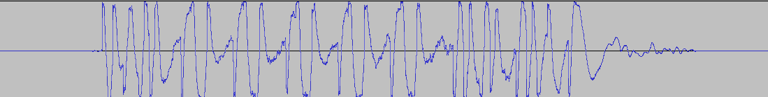
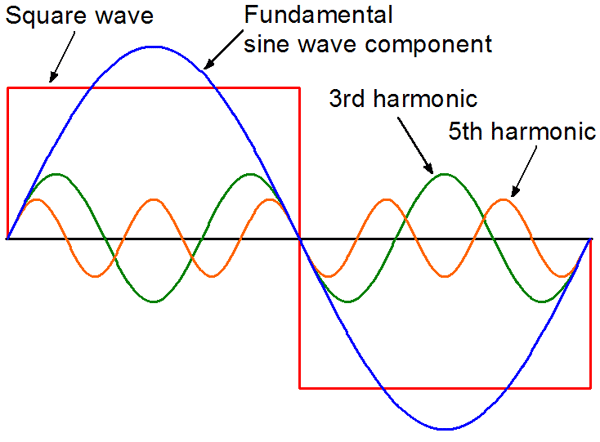
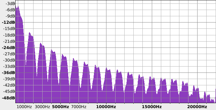
Unfortunately, the digital data that comes out of a stackmat looks nothing like a speech signal. To conceptualize what a phone does when it receives the square waves of the stackmat signal, it is necessary to visualize the square wave in terms of its component frequencies. This exercise is known as Fourier analysis. Thank you, Wikipedia:
To approximate the square wave (in red), add together all the component sine waves. The low frequency blue wave builds most of the shape, and the higher frequency waves serve to square out the corners. It’s hard to imagine what removing the blue wave from the signal would look like, but it should be clear that without that low frequency component, our signal is going to change dramatically.
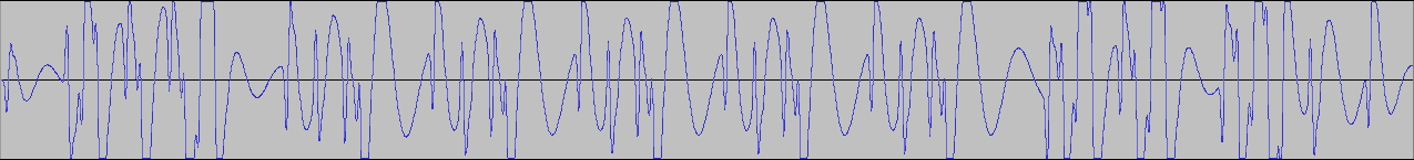
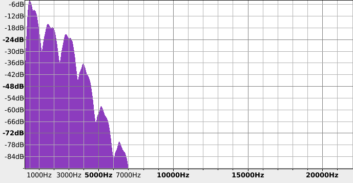
To simulate the effect of sending a signal through a channel designed for speech, we want to remove frequencies outside of the range 300 Hz to 3400 Hz. Audacity makes it easy to perform this experiment.
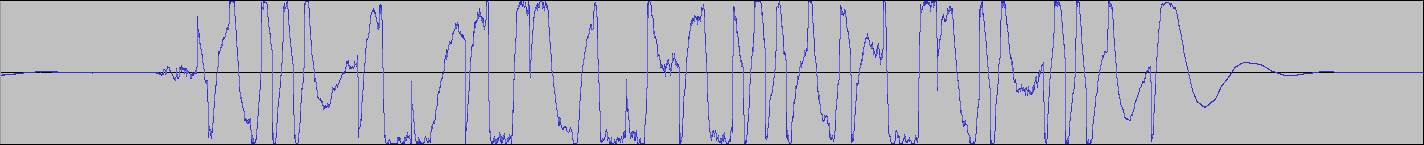
Now we apply a band pass filter that attenuates all frequencies between 300 Hz and 3400 Hz. Note that we’re not harshly cutting off all frequencies outside of this range, they are dampened instead. This is a reasonable approximation of what happens in the real world: devices gradually lose sensitivity to frequencies outside of their operating range, rather than dropping off entirely. The resulting signal looks very similar to the distorted signal we saw when plugging the stackmat into a phone!
If you’re interested in how different phones handle the stackmat signal, please see all these signals I’ve collected.
This begs the question: how do you translate the stackmat signal into a range of frequencies that phones do support? It turns out this problem (transmission of digital bits over a link designed for human voice) has already been solved. You use a modem!
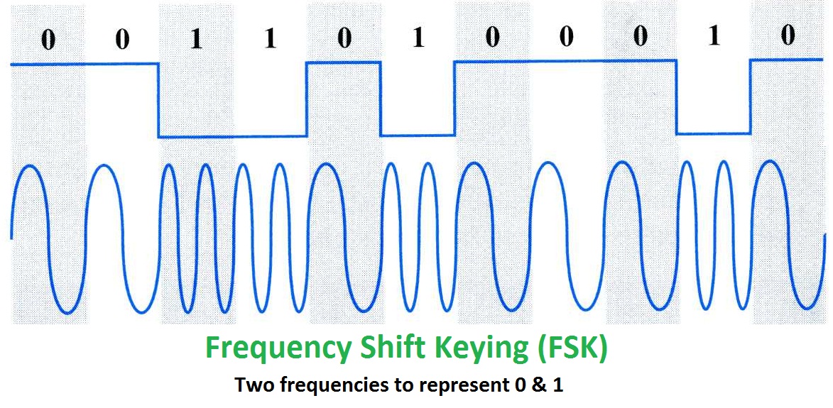
The word modem is actually a portmanteau of the words modulator and demodulator. The original modems used a modulation scheme called frequency-shift keying (FSK) that is surprisingly simple. Pick two distinct frequencies. Call one your mark frequency, it represents a binary 1. Call the other your space frequency, it represents a binary 0. Whenever your digital signal is a 1, send the mark tone, and whenever your digital signal is a 0, send the space tone. If the mark and space frequencies you chose are within the range of frequencies that phones support, you’re golden.
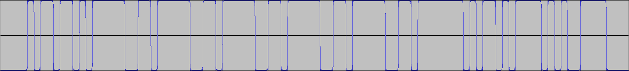
In the previous picture, the top signal represents the stackmat signal. The “mo” part of a modem would take this signal and produce the wavy bottom signal (FSK encoded). If we chose our mark and space frequencies correctly, then the FSK encoded signal is safe to run into a smartphone, which would then recover the original bits by doing frequency analysis in software.
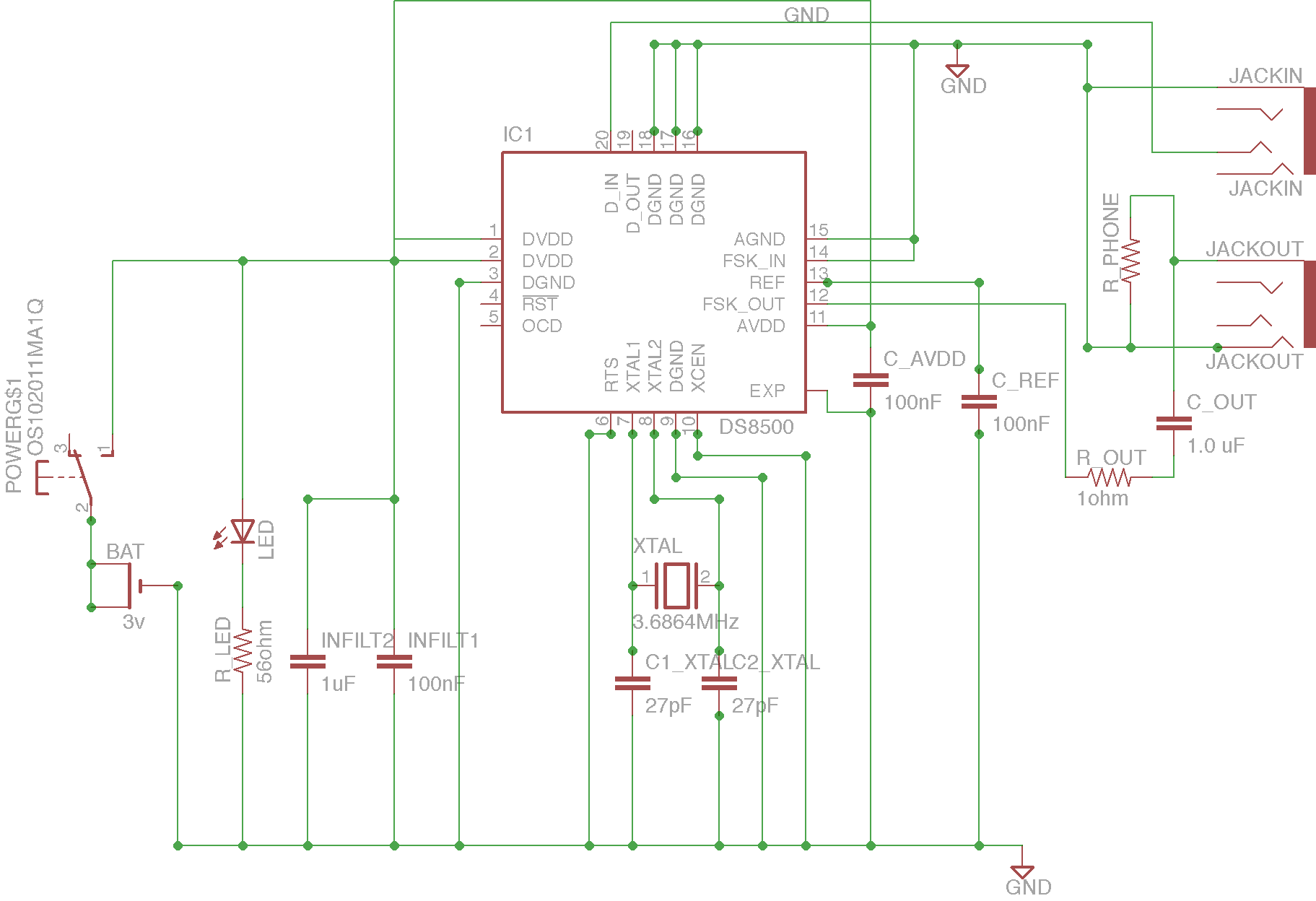
Eithan did some research, and discovered the DS8500 HART Modem. It produces frequencies of 1200 Hz and 2200 Hz, perfect for a phone. I was very skeptical that it would be able to speak the digital signal stackmats produce, but measurements of the stackmat’s digital output voltage were exactly the voltages the DS8500 data sheet asks for. The chip is only $12, why not give it a shot?
Unfortunately, using chips is not as simple as plug and play. Among other things, the DS8500 requires an input signal of 3.6864 MHz. Easy, run a current over a piece of quartz, and then filter the output of that through some capacitors. Also resistors. Apparently you need resistors everywhere (I’m convinced that resistors don’t actually do anything other than cost a few pennies and look cool). This was quickly getting out of hand.
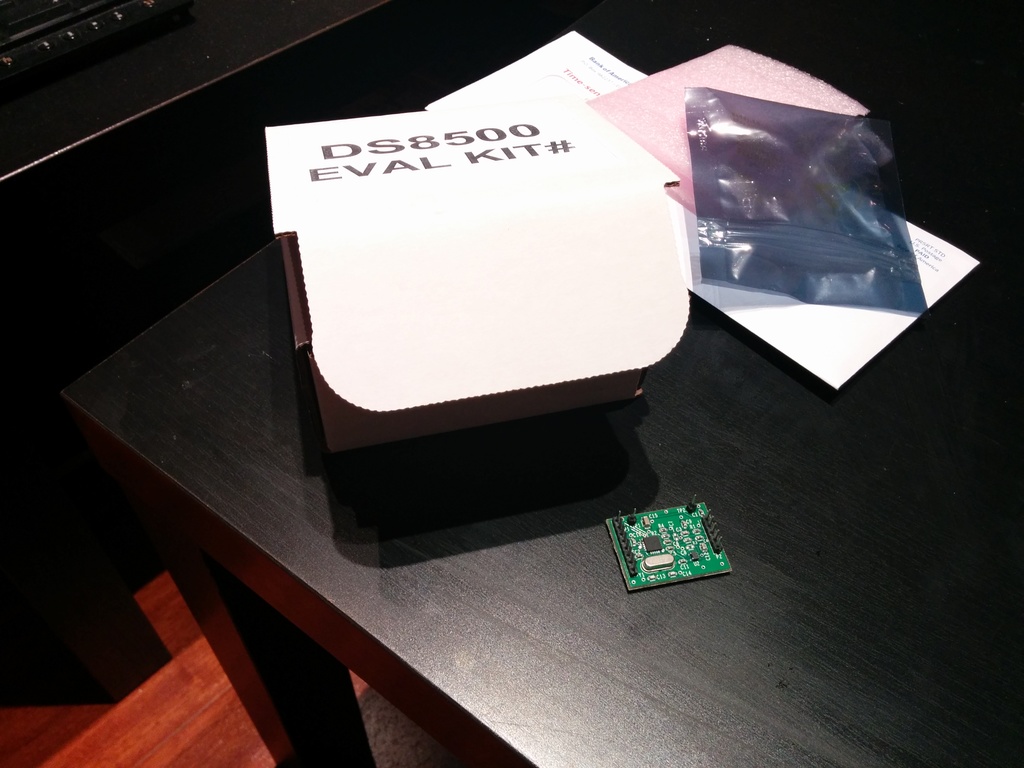
Suffice to say, reading the DS8500 data sheet and distilling that information into a working board requires a degree in EE. Eithan could do it, but he wasn’t sure he could get it right the first time. Fortunately, you can purchase an evaluation kit that has all the necessary components soldered to a DS8500 for you. For $46.86 after tax, the evaluation kit is a rip off (all the components on the board cost pennies, and the chip costs ~$12), but it let us verify the chip without the time and risk of designing and soldering our own board.
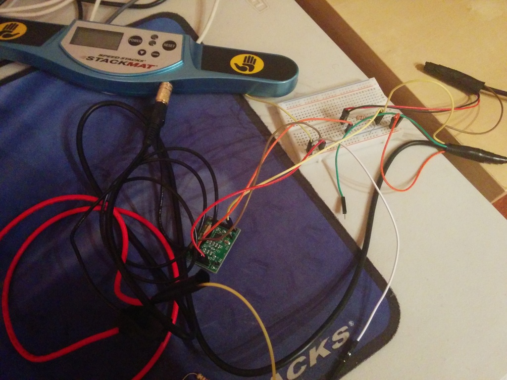
You can see a stackmat plugged into the modem above. I connected the output of the modem into my desktop, Nexus 5, and iPhone 3Gs and recorded the incoming signal.
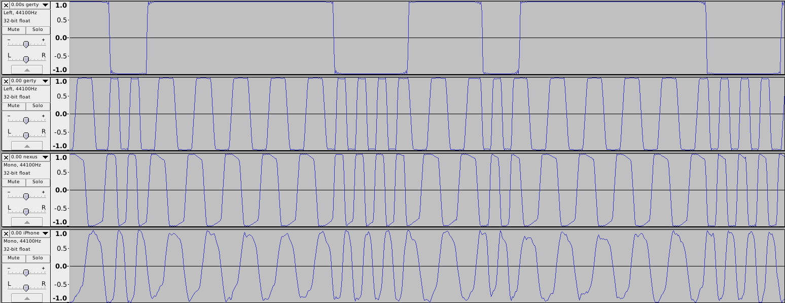
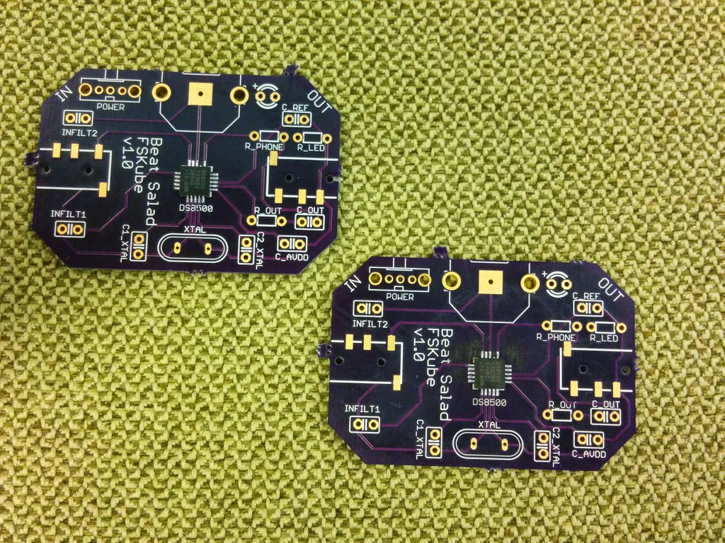
Success!!! The signals recorded by the phones are slightly distorted (we’re still not sure why), but it’s easy to tell where the 0s and 1s are. Having proven that the DS8500 does what we want it to, it was time to design our own board (Eagle CAD files available here).
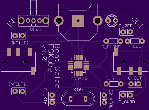
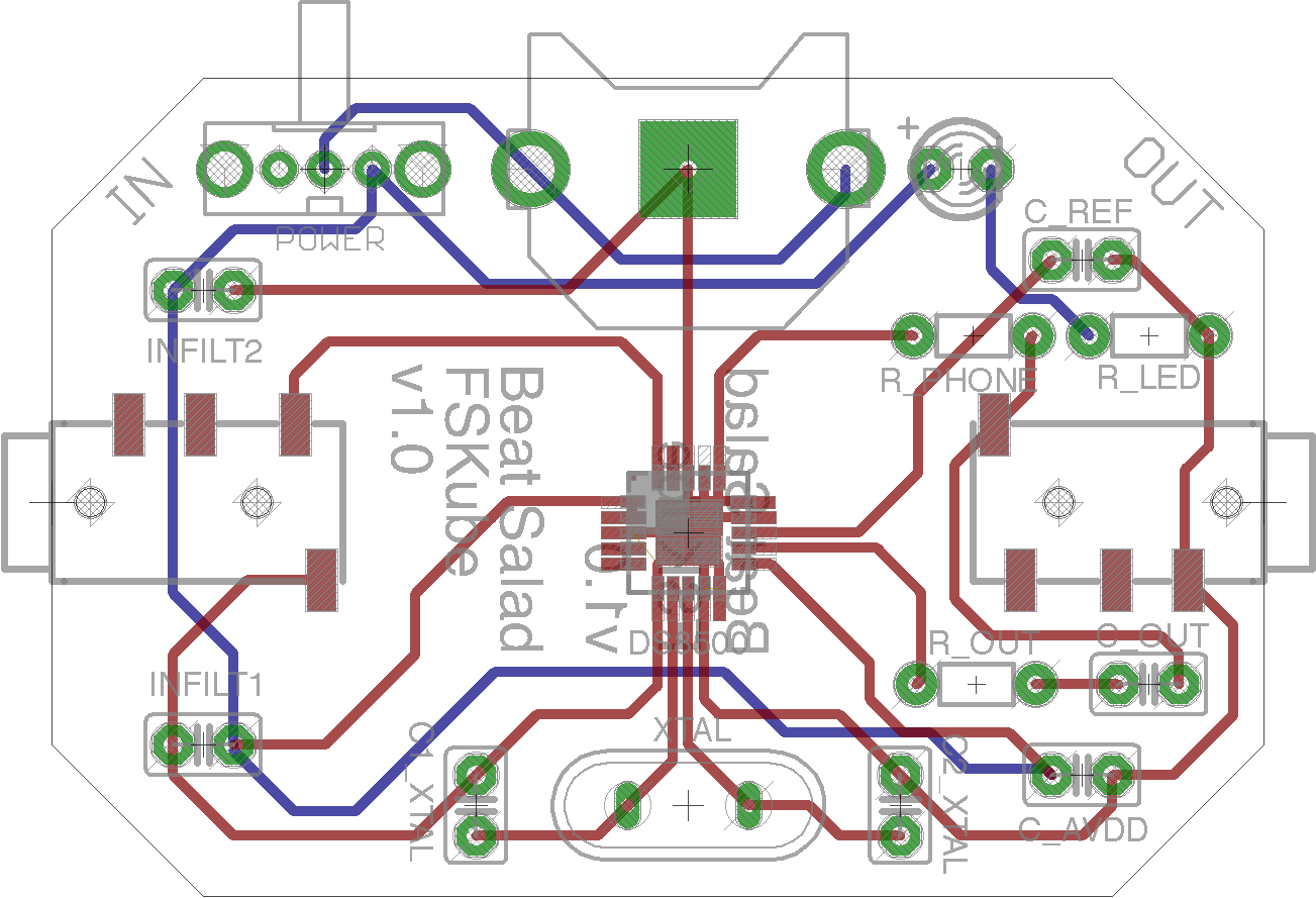
We used OSH Park to print the board, which required us to order a minimum of three boards. Eithan wisely insisted that we purchase at least two of each component. Everything for one board cost $26 (see our bill of materials). If we move onto mass production, the price should go down significantly.
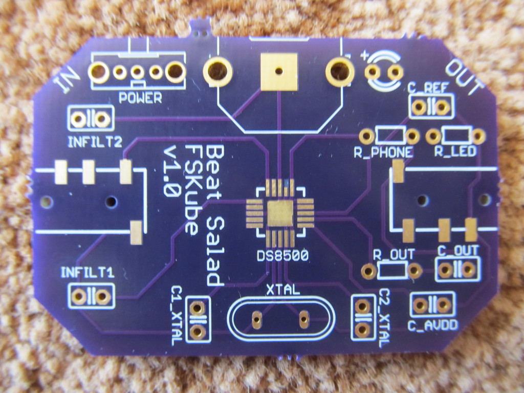
It wasn’t until everything arrived that we realized just how small the DS8500 chip is. We had no idea how we were going to solder it to the board.
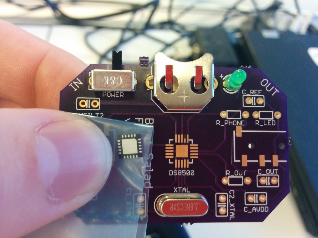
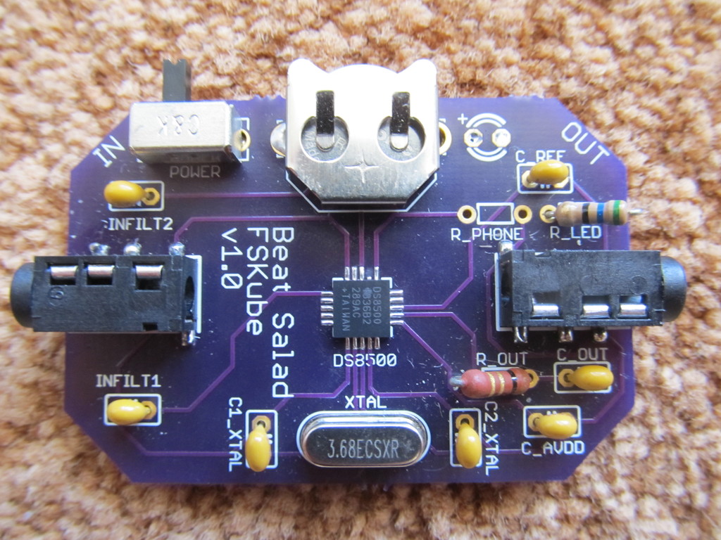
Fortunately, we found a coworker on the hardware team who does board work. Part of his job includes soldering these ridiculous TQFN packages. We gave him two of our boards and our two DS8500 chips. He attempted to solder the first one using a hot air gun, but the board cracked (our two layer board is a lot thinner than the boards he is used to working with). He soldered the second chip by hand, which meant that he couldn’t solder the “bellypad” (the large metal contact visible in the previous picture). Since the bellypad is labelled as a ground, and many of the contacts on the outside of the chip are also labelled as ground, we hoped that just soldering the outside would be good enough.
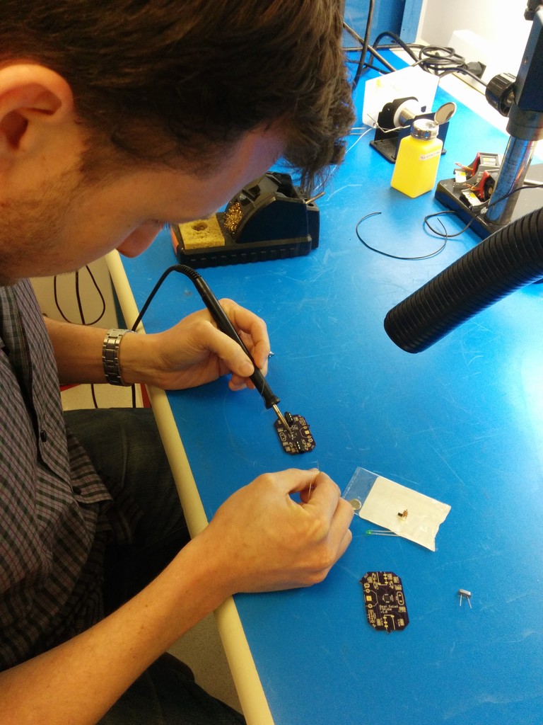
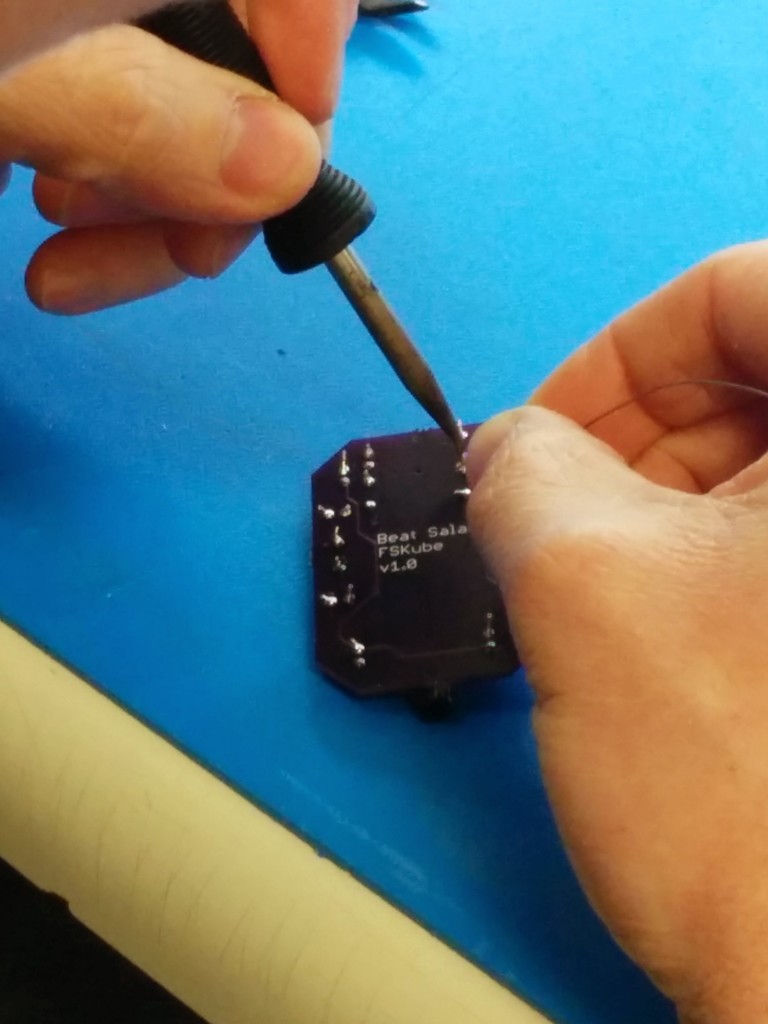
After that, it was a simple matter of letting Eithan do all the work.
Neither board worked at first. The board design called for an LED to indicate when the modem is turned on. The combination of modem and LED drew more power than our battery could supply. After removing the LED, the burnt board still didn’t work, presumably because the modem had been damaged by the heat.
This left us with one working board.
With our custom board in hand, I wrote code to demodulate the FSK signal (see jfly/fskube). All that code is written in C++, and compiles to Javascript with Emscripten. This is what powers the web demo at http://www.jflei.com/fskube/. Since the code is written in C++, it will be easy to develop an iOS app if we want to. Patricia Li, Darren Kwong, and I have already written an Android app using the Android NDK.
Demo
This is just the beginning. There is a lot of work to do before we can run a competition with our phones. I aim to start running small practice competitions with the Berkeley Cube Club in early 2015. I intend to see this project though until it can be used at a large scale competition such as US Nationals or Worlds.
Next steps
- Test on more devices, especially iPhones.
- Design a new board for mass production. If you happen to know anything about getting boards mass produced, please drop me a line! I’m very out of my element here.
- Integration with a live results system for WCA competitions.
Acknowledgements
- Eithan Shavit for teaching me everything I know about hardware and electricity (that’s still not very much, but that’s not his fault).
- Patricia Li for encouragement and for proof reading. She also wrote the skeleton of the Android demo app.